Views: 0 Author: Site Editor Publish Time: 2026-08-05 Origin: Site
Unplanned downtime and compromised product tolerances driven by roll degradation represent a significant, yet often preventable, capital leak in industrial forming, piping, and lifting operations. Identifying the root cause of uneven roll groove wear is rarely straightforward. Superficial symptoms frequently mask deeper systemic flaws in mechanical alignment, thermal management, or material selection. Treating the symptom without isolating the root cause leads to recurring failures and escalating maintenance costs. This guide provides a rigorous diagnostic framework to isolate the specific causes of uneven wear, evaluate the operational trade-offs of various corrective solutions, and establish a reliable maintenance protocol that protects equipment lifespan and product yield.
Mechanical Stress is the Leading Culprit: Unequal tension, improper machine setup, and misalignment account for the majority of premature and asymmetrical groove wear.
Design and Metallurgy Play Preventive Roles: Poorly designed groove geometries and incompatible roll metallurgy drastically accelerate wear, leading to slippage, scale buildup, and high friction.
Thermal Management Dictates Lifespan: Poor cooling performance accelerates material fatigue, leading to microcracking and eventual roll rib breakage.
Precision Diagnostics Inform ROI: Leveraging Non-Destructive Testing (NDT) and strict calibration protocols prevents the costly cycle of superficial repairs and recurring failures.
Table of Contents
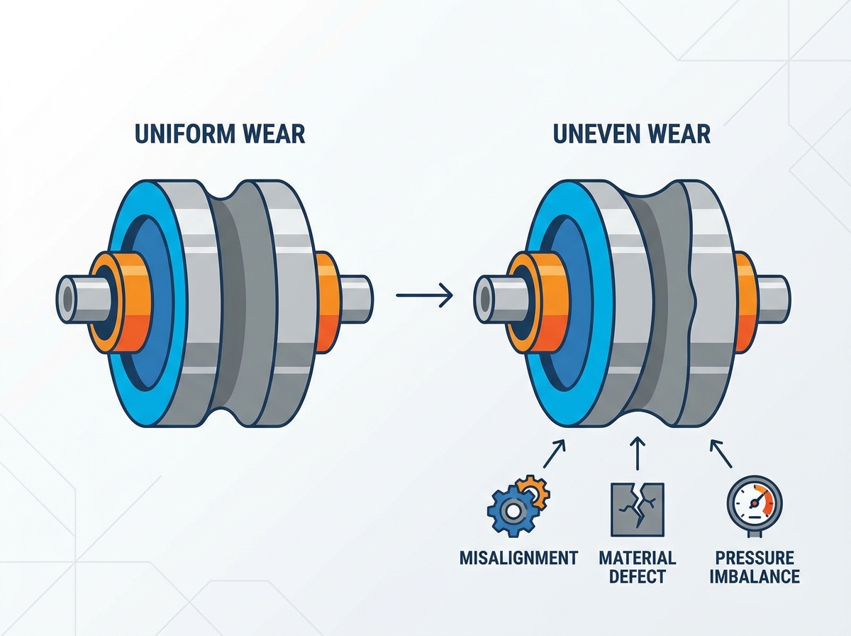
Understanding the physical failure mode of asymmetrical deformation is the first step in diagnosing equipment degradation. In specific cable and sheave applications, operators often refer to this phenomenon as groove seating. It occurs when mechanical forces remove material from the roll profile at varying rates across its surface. Instead of a uniform reduction in diameter, specific sections of the groove deepen or widen irregularly. This alters the intended geometry of the tooling, forcing the processed material to adapt to a flawed profile. We see this frequently in high-speed wire rod mills where even a fraction of a millimeter in deviation cascades into massive downstream issues.
Asymmetrical wear directly alters the forming profile of the workpiece. When the roll geometry degrades, the resulting products suffer from severe out-of-tolerance dimensions. This leads to immediate downstream assembly deficiencies. For instance, in pipe manufacturing, an irregular groove profile compromises the joining of pipes in grooved fittings. The pipe ends fail to align correctly, compromising seal integrity and structural stability. These dimensional inaccuracies drive up scrap rates, forcing operators to discard large batches of non-conforming materials. The compounding effect of these defects disrupts entire production schedules and compromises final product quality.
Wear Type | Physical Manifestation | Downstream Impact | Primary Detection Method |
|---|---|---|---|
Uniform Wear | Even reduction in groove diameter | Gradual shift in product dimensions | Routine caliper measurement |
Asymmetrical Wear | One side of the groove deepens faster | Severe out-of-tolerance, pipe joining failures | Laser profile scanning |
Localized Scoring | Deep scratches or gouges in specific spots | Surface defects on the finished product | Visual inspection, surface roughness testing |
Unequal tension in multi-line systems stands as a primary driver of asymmetrical groove seating. In sheave applications, multiple ropes or cables run through parallel grooves. If one or two ropes carry more tension than the others, they exert a disproportionate downward force into their respective grooves. This concentrated pressure accelerates material removal in those specific channels, causing them to wear deeper and faster than adjacent grooves. The resulting diameter differences cause synchronization issues, further exacerbating the tension imbalance. You can often hear this imbalance before you see it, as the equipment will generate a distinct rhythmic thumping.
Forming stress variances also force asymmetrical downward pressure into the grooves during metal shaping operations. When a metal strip enters a roll stand, variations in material thickness or yield strength create uneven resistance. The roll must absorb these fluctuating forces. If the stress concentrates on one side of the groove profile, that section experiences higher friction and mechanical fatigue. Application-specific issues, such as uneven torque in cold forming profile rolls, amplify this effect. When drive systems deliver inconsistent torque across the roll shaft, the resulting rotational stutter creates localized wear zones within the groove.
Verify incoming material thickness and yield strength consistency.
Check drive motor current draw for fluctuations indicating uneven torque.
Inspect multi-line tensioners for proper calibration and equal load distribution.
Measure the depth of each groove independently to identify seating disparities.
Calibration failures in roll grooving machines and forming mills guarantee premature tooling degradation. Misalignment occurs when the roll axes are not perfectly parallel or when the tooling does not align precisely with the material feed path. This forces the workpiece to enter the groove at an angle, creating severe point loading on the groove flanks. The mechanical interference generates excessive friction, rapidly stripping material from the misaligned contact zones. We often find that operators rely on visual alignment rather than precision dial indicators, which is a guaranteed path to failure.
Improper calibration directly results in dimensional deviations. Operators may set the machine to cut or form grooves that are too deep, too shallow, too wide, or too narrow. These incorrect settings permanently alter the wear pattern from the first production run. Furthermore, physical machine misalignment generates harmonic vibrations throughout the equipment structure. These vibrations cause the roll to chatter against the workpiece, accelerating localized wear patterns and leaving distinct chatter marks on both the roll and the finished product.
Improper initial design of the roll groove induces high stress concentrations that inevitably lead to failure. Suboptimal profiles, such as incorrect taper angles or inadequate groove radii, fail to distribute mechanical loads evenly. Sharp transitions within the groove geometry act as stress multipliers. When the workpiece contacts these poorly designed areas, the localized pressure exceeds the yield strength of the roll material, causing rapid deformation and wear. Engineering teams must calculate these stress points during the design phase, not after the roll has failed on the floor.
Inadequate structural clearances further compound design-induced wear. If the groove design does not account for material flow and expansion during the forming process, localized material crowding occurs. The workpiece becomes trapped against the groove walls, generating massive friction and heat. This crowding effect forces the metal to scrape aggressively against the roll surface, accelerating asymmetrical wear and severely damaging the surface finish of the final product.
Insufficient cooling creates severe localized thermal expansion across the roll profile. During heavy forming operations, friction generates intense heat at the contact points. If the coolant delivery system fails to dissipate this heat uniformly, specific sections of the roll expand more than others. These thermal expansion gradients alter the effective geometry of the groove during operation, causing uneven contact pressure and accelerated wear in the hottest zones. A blocked coolant nozzle can destroy a roll in a matter of hours.
Thermal stress directly degrades roll rib strength over time. Continuous cycles of rapid heating and inadequate cooling induce thermal fatigue within the metallurgical structure. This fatigue manifests as microcracking along the groove edges and ribs. As the microcracks propagate under mechanical load, they lead to groove chipping. If left unchecked, the compromised structural integrity results in catastrophic rib breakage, forcing immediate and costly line shutdowns.
Specific processed materials interact poorly with certain roll metallurgies, driving rapid degradation. Processing high-tensile steel grades requires roll materials capable of withstanding extreme contact pressures. If the roll metallurgy lacks the necessary hardness or wear resistance, the high-tensile workpiece will simply machine the groove away during operation. This metallurgical incompatibility guarantees a short tooling lifespan and constant dimensional drift. You cannot run advanced high-strength steels on standard cast iron rolls and expect them to survive.
The phenomena of slippage and heading-up in rough rolling heavily influence wear patterns. Friction coefficients dictate how the material moves through the roll bite. If the friction is too low, the material slips against the groove, causing abrasive wear. Conversely, certain steel grades are prone to heavy iron scale generation during processing. This iron oxide scale acts as a harsh abrasive compound. As it accumulates within the groove profile, it grinds away the roll surface unevenly, destroying the intended geometry.
Superficial re-machining presents severe risks to ongoing operations. When maintenance teams attempt to restore a worn groove, they must remove enough material to reach sound, undamaged steel. Failing to completely remove microcracks during groove re-machining leaves latent defects within the roll structure. These remaining stress concentrators rapidly propagate into uneven wear or catastrophic chipping immediately upon redeployment. Skimming the surface to save time always costs more in the long run.
Over-machining without verifying structural rib limits leads to rapid mechanical failure. Each time a roll is re-machined, the supporting ribs become thinner and weaker. If maintenance personnel exceed the safe minimum thickness for the ribs, the roll loses its structural rigidity. During operation, these weakened ribs deflect under load, causing severe asymmetrical wear and eventually snapping off entirely.
Establishing baseline metrics for groove geometry is critical for accurate visual and dimensional inspection. Maintenance teams must routinely measure the groove profile to identify early signs of uneven wear, localized scoring, or unusual widening. Operators should also monitor downstream product quality, as pipe-fitment defects often serve as the first indicator of roll degradation. Identifying unusual vibration patterns during operation can also point directly to misalignment or bearing wear affecting the roll position.
Utilizing Non-Destructive Testing (NDT) provides visibility into subsurface defects before they cause failure. Ultrasonic testing and magnetic particle inspection allow technicians to detect latent microcracks beneath the groove surface. Implementing these tests during routine maintenance prevents the accidental redeployment of compromised rolls. Correlating wear patterns with process monitoring data further isolates the root cause. By analyzing temperature logs, tension sensor outputs, and motor load anomalies, engineers can pinpoint the exact operational condition driving the accelerated wear.
Clean the roll surface thoroughly to remove all scale and coolant residue.
Perform a visual inspection for obvious scoring, chatter marks, or rib deflection.
Use a profile gauge or laser scanner to measure the groove geometry against OEM specifications.
Conduct magnetic particle inspection to identify surface-breaking microcracks.
Perform ultrasonic testing to detect subsurface defects and verify remaining rib thickness.
Transitioning to high-speed steel (HSS) or applying advanced carbide coatings directly addresses material incompatibility. These upgraded materials provide superior hardness and thermal stability, allowing them to resist the extreme friction generated by high-tensile steel grades. Specialized coatings also modify the friction coefficient, reducing slippage and preventing scale adhesion. The primary trade-off involves balancing the higher upfront capital expenditure of these advanced materials against the extended mean time between failures (MTBF) they provide.
Material/Coating | Primary Benefit | Best Application | Operational Trade-off |
|---|---|---|---|
High-Speed Steel (HSS) | Exceptional wear resistance and hardness | High-tensile steel forming | Higher initial procurement cost |
Tungsten Carbide Coating | Extreme surface hardness, prevents scale adhesion | Rough rolling, high-scale environments | Susceptible to impact chipping if mishandled |
Nodular Cast Iron | Good thermal conductivity, cost-effective | Standard structural steel rolling | Rapid wear when processing harder alloys |
Integration of closed-loop tension controllers and laser alignment tools eliminates human error in machine setup. These systems continuously monitor and adjust mechanical forces, ensuring equal tension across multi-line systems and preventing groove seating issues. Automated alignment prevents the point loading that drives asymmetrical wear. This solution is highly scalable for multi-stand rolling mills, though it requires careful integration with existing PLC and SCADA control architectures.
Modifying the groove design profile optimizes stress distribution and eliminates localized crowding. Engineering teams can adjust taper angles, increase transition radii, and ensure adequate structural clearances for material flow. This resolves systemic design-induced wear at the source. Implementing this solution requires dedicated engineering resources and initial tooling modifications, but it permanently eliminates wear patterns caused by poor initial geometry.
Upgrading coolant delivery systems ensures uniform thermal dissipation across the entire roll profile. This prevents the thermal expansion gradients that warp the groove geometry during operation. Implementation realities often require retrofitting high-pressure nozzles and upgrading fluid filtration systems. Clean, high-pressure coolant prevents nozzle clogging and ensures consistent heat removal, directly preventing thermal fatigue and microcracking along the roll ribs.
Comprehensive alignment and system overhauls carry the risk of extended downtime. Facilities cannot afford to halt production indefinitely for maintenance. To mitigate this, management should mandate phased implementation during scheduled preventative maintenance windows. Utilizing modular alignment jigs and pre-calibrated assemblies allows technicians to execute faster calibration, minimizing the impact on production schedules.
Inaccurate post-repair calibration easily leads to immediate recurring wear, wasting the entire repair effort. Facilities must mitigate this by mandating third-party NDT verification on all repaired tooling. Technicians must enforce strict adherence to OEM dimensional tolerances before returning any roll to service. Furthermore, operator resistance to new automated tensioning protocols can undermine equipment upgrades. Comprehensive training programs focused on transitioning from manual feel to data-driven calibration ensure operators utilize the new systems effectively.
Uneven roll groove wear functions as a systemic indicator of mechanical, thermal, design, or operational imbalance. It is not merely an inevitable consequence of heavy production. Facilities must prioritize their interventions based on hard diagnostic data. Addressing alignment and tensioning provides immediate mechanical fixes, while evaluating metallurgical upgrades and groove design modifications resolves long-term material incompatibility issues.
Founded in 2007, Anhui Huanbowan High Speed Steel Mill Roll specializes in high-speed steel rolls and roll rings for plate, strip, bar, wire, steel tube, and section-steel rolling applications. Supported by integrated casting, heat-treatment, machining, quality-control, and technical R&D capabilities, the company helps rolling mills select suitable roll materials and designs for demanding production conditions and long-term wear-control requirements.
Initiate a comprehensive dimensional audit of all current roll inventory to establish baseline wear metrics.
Schedule mandatory Non-Destructive Testing (NDT) for all high-risk and frequently utilized tooling.
Consult with equipment manufacturers to evaluate automated alignment retrofits for existing mill stands.
Revise maintenance protocols to include strict verification of structural rib limits before any re-machining occurs.
A: The most frequent causes are unequal mechanical tension, uneven stress distribution during the forming process, and improper machine misalignment. These factors force asymmetrical downward pressure into the grooves, accelerating localized material removal and altering the intended tooling geometry.
A: Groove seating occurs primarily in sheave and cable systems where unequal rope tension forces specific ropes deeper into their grooves. This unequal pressure causes those specific channels to wear faster than adjacent ones, creating severe synchronization issues and accelerating overall equipment degradation.
A: Inadequate cooling causes localized heat buildup and severe thermal expansion gradients. This continuous cycle of rapid heating and poor cooling induces thermal fatigue, forming microcracks along the ribs. Under mechanical load, these microcracks propagate, eventually causing the compromised ribs to break entirely.
A: Yes. Harder, high-tensile steel grades require superior roll metallurgy to withstand extreme contact pressures. Incompatible materials alter friction coefficients, causing slippage. Additionally, certain grades generate heavy iron oxide scale, which acts as an abrasive compound that rapidly grinds away the groove profile.
A: Improper groove radii, incorrect taper angles, and sharp transitions act as severe stress multipliers. These suboptimal designs fail to distribute mechanical loads evenly, causing localized material crowding and high friction zones that rapidly deform the groove under normal operating pressures.